
Convex
Connecticut Valley Electric Exchange (CONVEX) deserves mention on this site because it's headquarters was originally located in a hardened underground bunker designed to protect the operators and equipment from natural disasters and nuclear attack.
One of our contributors toured the bunker in the early eighties with a professional organization. He recalls going down several flights of stairs and entering the facility through a large blast door. Inside was a large room with a huge map of the area's power grid showing transmission lines, generating plants and substations. Reportedly the facility was hardened against blast, fallout and EMP and could operate "buttoned up" for up to 15 days. The original New England Power Exchange located in W. Springfield, MA had a similar facility.
Convex is a transmission operator for Connecticut and western Massachusetts utilities originally located in Southington, CT. CONVEX operates its transmission system, 24 hours a day, 365 days a year. At present, the organization operates as the 2nd largest (in load served) Local Control Center (LCC) in New England. The organization monitors energy demand on the system and its impact on power quality throughout the CONVEX system. CONVEX helps utilities to serve more than 1,700,000 customers. The members of the organization include The Connecticut Light and Power Company, Western Massachusetts Electric Company, Groton Utilities, Bozrah Light and Power and Chicopee Electric Light.
In service since January 1, 1964, CONVEX (Connecticut Valley Electric Exchange) is an organization of
As a Transmission Operator, CONVEX’s primary function is to ensure the safe, reliable and economic operation of the CONVEX transmission system, 24 hours a day, 365 days a year, no matter what the conditions. This responsibility is carried out in conjunction with ISO-NE by evaluating, coordinating, and responding to planned and dynamic changes in the connectivity of the transmission system, ensuring that reliable service to the electrical distribution system is maintained at all times. CONVEX also monitors energy demands on the system and their impact on power quality throughout the CONVEX system, and performs dispatching functions, including the implementation of emergency actions when necessary, to ensure power quality remains within acceptable tolerance at all times.
The heart of CONVEX is its
From the history of the Connecticut Light and Power Company:
"In 1960, CL&P put into operation a unique, underground electric dispatching center designed to withstand natural disasters and the danger of radioactive fallout in the event of nuclear war. The center, located in Southington, Connecticut, became the nerve center of the company's generation and transmission system. In 1964, the electric energy dispatch and transmission system was regionalized, with the creation of the New England Power Pool. At that time, CL&P’s Southington facility became known as the Connecticut Valley Electric Exchange (CONVEX). Also in 1964, the company's Board of Directors promoted Sherman R. Knapp to chairman and elected Paul V. Hayden to succeed Knapp as president."
DESCRIPTION OF THE FACILITY
On February 8, 1960, the Load Dispatching Department of the CT Light and Power Co. moved into a new and more spacious quarters. This in itself is not too unusual. The thing which is unusual is the fact that this Dispatch Center is designed for operation in the atomic age. It is one of the first of its kind, it this country, equipped for continuous operation even through a heavy fallout condition.
MAIN BUILDING – The floor of the main building, measuring some 90’ x 100’, is 16’ underground. The walls are 12” reinforced concrete. The ceiling is of 12” reinforced concrete poured on a steel deck. The roof of the building extends only 18” above ground. By virtue of its low silhouette, the main building should successfully withstand the effects of a 3-megaton bomb having a ground zero as close as 3 miles.
By using the excavated soil for banking against the side walls to deflect an aerial blast it was possible to avoid a full depth excavation. Although the excavation costs for an Underground building are greater than an above ground level structure, the use of poured concrete
Substantially offset the cost of a finished brick structure above ground. It has been recognized that, in case of a direct nuclear bomb hit no building would emerge undamaged. Therefore, the design of this structure was based upon resisting the shockwave and radiation of a 1 megaton bomb burst about 1 1/2 miles away and a 20 megaton bomb about 3 miles distant. According to the publication "The Effects of Nuclear Weapons" by the United States Atomic Energy Commission, the anticipated damage from such an incident would be minor and should not affect operations.
SUPERSTRUCTURE
The building is entered through a small superstructure set upon the building proper. This brick-faced structure besides serving as an entrance lobby also contains a training room with a seating capacity of 35. The training room is equipped with a chalkboard, screen and projector's. This superstructure is not an integral part of the main building , it is designed to be expendable and would be destroyed by a strong shock wave, of a nearby nuclear detonation.
GENERAL
The Dispatching Center is always locked. To gain admission to the building, a prospective visitor goes to the front door and presses a button on the intercom unit located to the right of the door. This sounds a single-stroke gong and lights a light on the intercom unit built into the Load Supervisor’s telephone console. The conversation establishes the visitor’s identity and his business, At the same time a closed circuit television camera is focused on the visitor through the heavy glass doors. This camera is connected to a 17" receiver located over the meter panels in the Dispatching Room. If satisfied orally and visually the Supervisor operates a small level which unlocks the door. Turning left in the Lobby, the visitor descends down an L-shaped stairway to the Lower Level , This stairway was designed to minimize any blast effect. At the foot of the stairs is an radiation resistant door madef 1/4" steel plates front and r ear, the space between the steel plates is filled in with 3" of concrete. This is the first of two doors comprising the front air lock. There is a similar air lock at the rear entrance. Inner doors are kept open except during emergency conditions. To the right of the front air lock is a hallway leading to the storage room and emergency storeroom. The latter room contains cots and sufficient food to enable the entire personnel of 17 to subsist for a minimum period of 14 days without outside contact ,
EMERGENCY ROOM
Just off this hallway is the emergency room. Here the sleeping cots will be set up in case of any emergency. In the far right corner hidden by an accordion door is the combined electric stove and refrigerator unit. Folding tables and chairs are permanently kept in this room. To the left of the room is the emergency escape exit consisting of a rectangular concrete shaft Leading up to the ground level. A steel ladder reaching to ground level is anchored to one wall. Entrance is gained through a rubber sealed door some 3 feet above floor level. Just inside the door are "knockout, boards" sealing off the Door opening. The entire exit chamber is filled to the top with dry sand. The top of the shaft is sealed with a light weather- capping which is flashed into the roof. In case a blast should block off both front and rear stairways the emergency exit would come into use , Removal of the "knockout boards" will allow the sand to run into the emergency room and expose the ladder , The weather- cap is light enough to permit easy lifting from the ladder.
EQUIPMENT ROOM
Adjacent to the Emergency Room is the Equipment Room. Located here are the oil-fired boiler and the air conitioning and filtration system. Ninety percent of the air is recirculated and enters the unit through louvers in the hallway. It then passes through a fiber glass prefilter and on through the cooling coils. From here the air passes through the main electrostatic precipitator. The ten percent makeup air is pulled from outside the building through special air inlets and passes through an electrostatic precipitator and then merges with recirculating air just ahead of the main precipitator. Next the air passes through another fiber glass filter and on to an activated charcoal filter. From here the circulating fan supplies the various offices and Dispatchers Room. This filtration will permit continuous use of the outside air even during fallout periods. Should blast damage block off the air intakes, there is sufficient cubic capacity in the building to last for several days just on recirculation. Whenever necessary, oxygen tanks located in back of the system diagram board can be bled into the building to revitalize the air supply. HVAC gear is located in the Equipment room and consists of a 10-ton and a 15-ton compressor feeding the cooling system. The entire main building operates at a controlled humidity of 40%. Just off the Emergency Room is a 1000 gallon water tank fed from a deep well located under the building proper. In case of fallout the main water supply from the city reservoir will be shut off within the building and all water requirements will be supplied by this tank and a deep well pump. The tank is drained and refilled monthly to change the water and to test the feed pump.
EMERGENCY GENERATOR ROOM
The emergency generators are located in the right front section of the building. A 10kw AC generator supplies the communication requirements consisting of carrier, microvave and radio. The automatic dispatching equipment is also powered by this unit. Emergency power for the rest of the building is supplied by a 45-Kw water--cooled diesel unit generating at 208v – 3-ph. This is ample to care for the main building requirements. Both of these units start automatically whenever the building power supply is interrupted. A 8000 gallon tank buried in the yard supplies fuel oil for both the diesel unit and the heating boiler.
OFFICES
From the front a corridor runs down the right side of the building leading to the Clerical Office in which the PBX Operator), Stenographer and Exchange Calculator are located. Other offices are provided for the Load Forecaster, Chief Dispatcher and Superintendent.
UTILITY ROONS
The Telephone Room contains all the automatic dialing and trunk line equipment is located at the right rear. Next comes the Repair· Room equipped for electrical, mechanical and meter repairing. In the left hand corner of this room is the main service cubicle"
Power is supplied to this unit from several sources. The first is a 150-Kva,- 3PH, 208V transformer fed from the 4.8-Kv bus of the adjacent Southington Substation. The second feed is from a similar transformer connected to the 14.4-Kv bus ofthe substation.
CABLE ROOM
The cable room contains the transmitters for the company radio system and also the emergency unit for communication with adjacent utilities. Here too are the carrier units, the microwave units and components of the electronic analog computers.
REAR ENTRANCE
The rear entrance door has an electric lock. An intercom unit provides oral contact with the Load Supervisor's position. There is no television camera at the rear entrance. Beyond the entrance door is the first 800 pound door of the rear air lock. This door is located at the first anding level. The second 800 pound door opens into the Dispatchers! Room. Beyond the rear entry is the Decontamination Room with its shower Equipment. Finally, there is the pump room. The sump tanks 4 ft in diameter by 71” deep. One is for clean water and the other for sewerage; The clean water is pumped above ground to a settling area, The sewerage is pumped up to a septic tank connected to leaching lines.
DISPATCHING ROOM
The Dispatching Room measures 40' x 53 ½’.It has a curved aluminum system diagram board measuring 12' x 68’ which is painted Load Dispatcher’s Green. In front of this board are two 508A telephone desks. The center desk is the regular switching position. The right hand desk is the emergency position while the left hand position is for future expansion.
![]()

Early picture of the original building atop the Convex bunker in Southington, CT. This building housed a staircase used to access the facility and also contained a training classroom.

Cut-away view of the Convex bunker.

Underground CONVEX DIspatcher's Room, 1967


The building above was built on top of the Convex bunker
in the early 70s.

The outer blast door weighing 800+ pounds is made up of two
1/4" steel sheets with concrete sandwiches in between.

Decontamination Shower

Cafeteria area.

This 45kW diesel generator provided
emergency power.

Water was supplied by the city main
and from an deep well.
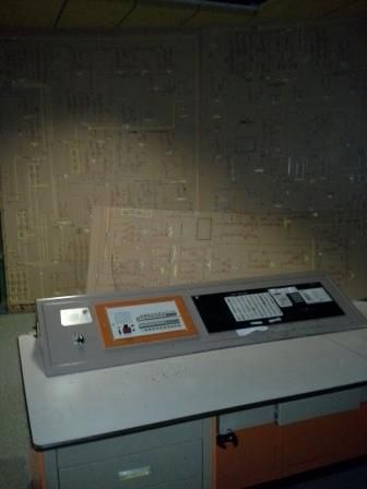
 This was the original large system board at one end of the facility.

Close up of the original board with one of the
control positions in the foreground.
Another control position.
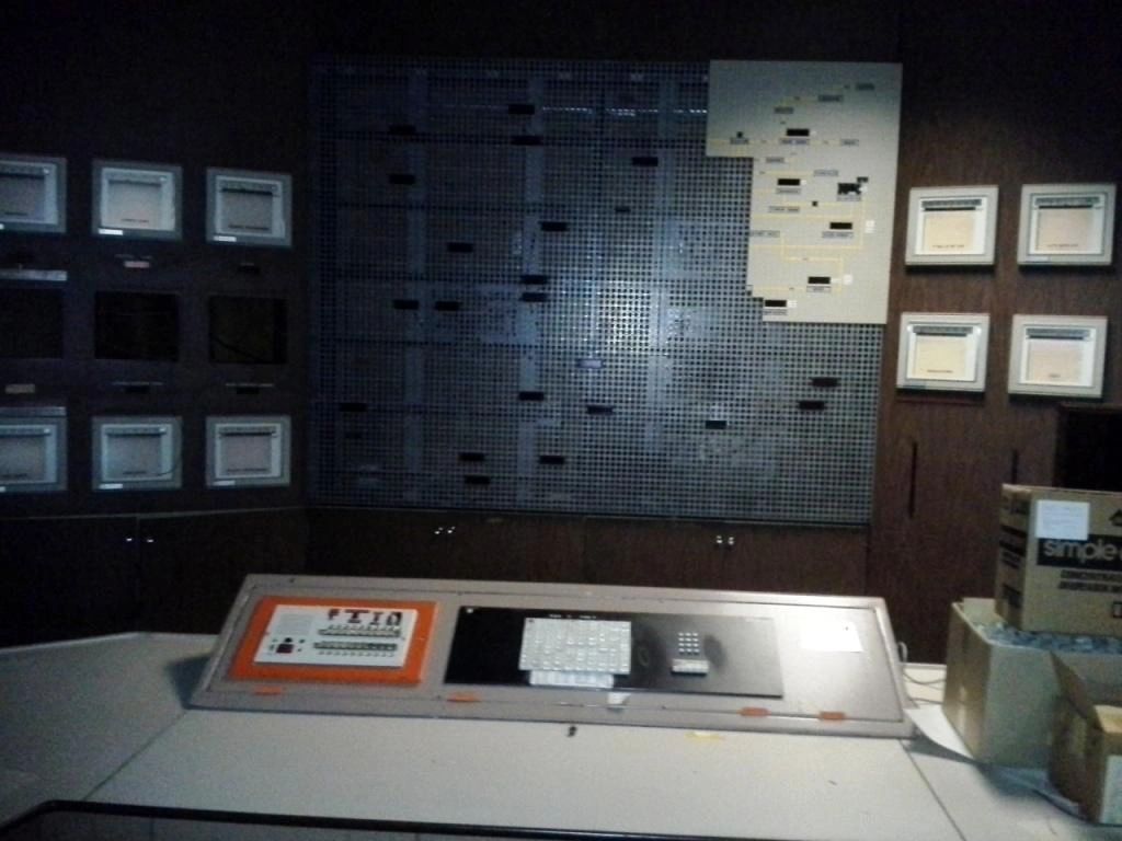
This is the newer of the two boards.

Close up.

This door leads to the escape tunnel.

This is what we found when we opened the door to the escape tunnel!
The tunnel was filled with sand to prevent it from collapsing during
an atomic attack. The brackets in this photo originally held an ax
and a pry bar which were used to break the wooden slats.
This allowed the sand to spill out into the room allowing access
to the escape ladder!

Communications panel.
